Most audio gear is built around a computer. There are plenty of USB audio interfaces on the market, and nearly all of them expect you to control routing and levels from software. Only at the professional end does control move to dedicated mixing hardware. I wanted the latter for my desk, and getting there meant replacing the firmware on a device I’d bought.
Why not software?
Software-managed audio is awkward without a dedicated desktop. If I plug a different laptop into my home setup, the controls don’t come with it. The round trip through the computer also adds noticeable latency compared to a hardware mixer.
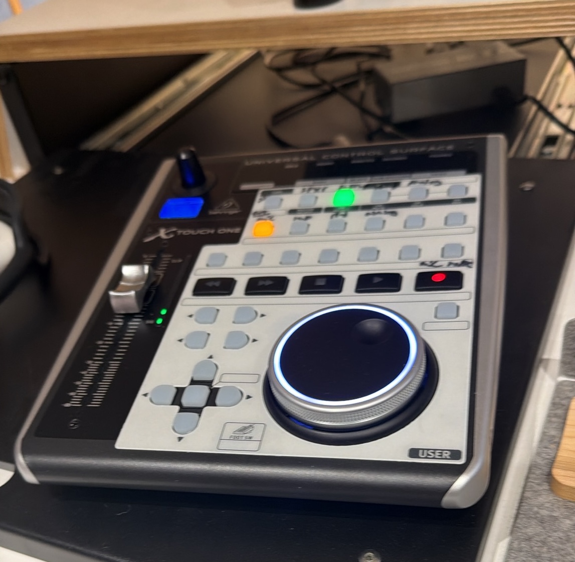
With that in mind, I got a Behringer X-Touch One. It’s a small control surface with a single motorized fader that fits on a desk and speaks MIDI. The plan was to pair it with a Midas M32C to manage routing and levels across speakers, a laptop, a tablet, and a microphone.
This pairing seems uncommon, and I found little discussion of it. Physically connecting the two was easy: a USB MIDI host adapter bridges the surface’s MIDI-over-USB to the mixer’s DIN MIDI port.
The stock firmware
The harder problem was behavior. The surface ships with around nine modes that determine which MIDI messages it sends and receives. Most of them target DAW software. The ones meant for hardware, such as those speaking the Mackie Control protocol, offer a single layout that pages through channels in a way that didn’t map naturally onto my setup.
The usual advice is to put a computer between the two devices to translate MIDI messages. That felt like overkill, and it brought back the dependency I was trying to remove. Instead, I set out to flash custom firmware.
Getting in
I started with the four or so firmware releases Behringer has published. Then I attached an SWD debug probe, a Raspberry Pi debug probe, to the ARM microcontroller. The chip’s read protection kept the bootloader out of reach. Even so, the view into the rest of the memory space made it much faster to understand how firmware updates worked.
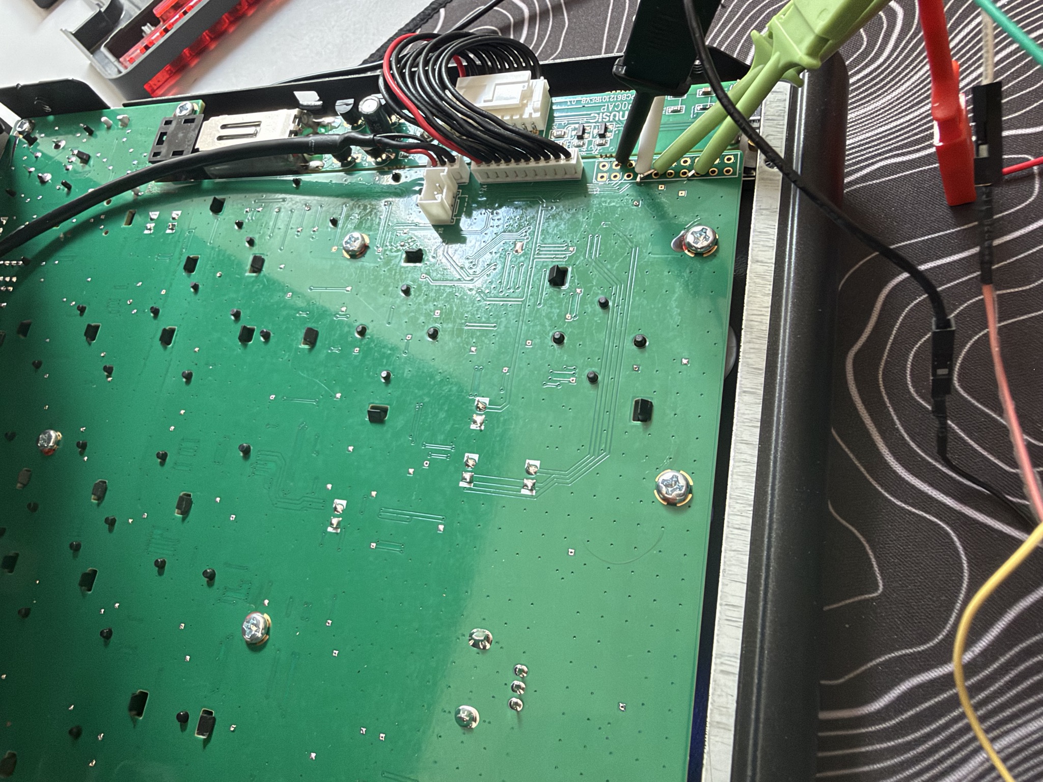
Some technical details:
- Layout. The firmware is the ARM code the processor executes directly. It occupies the user-program region of flash. A fixed bootloader sits earlier in the memory image and handles early boot and firmware updates.
- Encoding. The image is XORed with a repeating 2048-byte key. The key shows up in the statistical frequency of recurring bytes, and it can be read almost directly out of the zero padding at the end of the published updates. The final sector of version 1.10 yields all but 10 bytes of it.
- Update protocol. The encoded image is split into chunks, each with a truncated CRC32 checksum. The device validates each chunk’s checksum, decodes it, and writes it to flash.
The key was enough to read the firmware, but not to write it, because the checksum mixes in additional constants held in the bootloader. To get them, I built a single-block image whose only job was to copy the bootloader into readable memory. I then repeatedly tried to flash it while brute-forcing the checksum until the device accepted it. Once the image ran, I read the bootloader out with the probe. That gave me everything needed to generate and load arbitrary code onto the surface.
The result
With custom firmware, the surface now sends the MIDI messages I want, mapped to the channels and routing that feel natural for my setup. It also unlocked hardware features the stock firmware never exposed, like custom colors for the screen and button lights.
Lowering the bar
It’s exciting to see the barrier to controlling and customizing the devices around us coming down. The effort is still non-trivial: this time I opened the device and attached a debug probe. In hindsight, the probe was a shortcut rather than a requirement. The same one-block program could have sent the bootloader back over USB instead. That route is fiddlier, but it needs nothing beyond the published updates. You’d still want a harness to power-cycle the device and put it into flash mode, but that’s a much lower bar than opening the case.